Tech Report
Multi-viscosity mixing in a Triple-Shaft Mixer
Technology Brief
This bulletin provides a step-by-step look at atypical multi-shaft mixer application which demonstrates the system's processing flexibility in terms of mixing, heating, cooling and deaerating batch material at different viscosity stages.
Mixer flexibility in terms of viscosity range
Multi-shaft mixers comprised of two or more independently-driven agitators working in tandem are well-known for their wide ranging uses in multi-viscosity mixing applications. In such processes, the batch material undergoes many changes in viscosity, perhaps starting out as a thin liquid that gradually be comes more viscous with the addition of solid raw materials and/or lowering of temperature. Some applications will reach a viscosity peak mid-processing and finish as a low-viscosity fluid. In all these stages, the mixer must be capable of delivering good turnover and effective heat transfer, impart the required shear input and quickly deaerate batch product, as necessary.
Most multi-shaft mixer configurations consist of a low speed anchor agitator which compliments one or two high speed devices, such as a sawtooth disc-style disperser blade or a rotor/stator assembly. The disperser and rotor/stator are particularly effective at fast powder wet-out, dispersion and particle or droplet size reduction. However, both designs are inherently limited in terms of viscosity range. On its own, a disperser blade will produce acceptable flow patterns for products up to 50,000 cP; the rotor/stator up to around 10,000 cP. The anchor agitator therefore performs the crucial role of promoting bulk flow, encouraging viscous product to move towards the high speed devices and constantly removing batch material from the vessel walls to optimize heat transfer. In combination, all three agitators can handle formulations as high as a million centipoise.
Sample batch procedure
The following summary of a polymer dispersion test provides a step-by-step look at a typical multi-shaft mixer application and a good indication of the flexibility possible with this type of mixer.
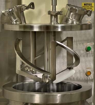
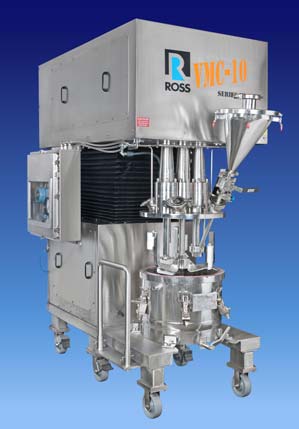
- Mixer specs: 300-gallon Triple-Shaft Mixer with Three-Wing Anchor (max speed:30 rpm), High Speed Disperser (14" saw-tooth blade, max speed: 1,090 rpm) andHigh Shear Mixer (7" rotor and slotted stator, max speed: 1,800 rpm) equipped with a powder injection manifold. All drives are independently controlled and offer a 10:1 variable speed ratio. The mixer is equipped with a jacketed vessel as well as Teflon scrapers on the anchor agitator.
- Phase 1, mixing: 150 gals. of base oil is added to the vessel and heated to 350oF.The anchor is run at 25 rpm and as the liquid begins to warm, 300 lbs. of solid rubber polymer is added to the mixer. The disperser is started at 1,090 rpm to initially reduce the solid particles into smaller pieces that could flow through the stator openings of the high shear mixer. Once the polymer has been broken down sufficiently, the rotor/stator is turned on to start the fine grinding process.Soon, the batch reaches the target temperature and at this point, the rotor/stator is doing most of the high shear work; the saw-tooth disperser blade is mainly contributing to batch circulation. Meanwhile, the anchor is constantly moving material from the vessel perimeter to the interior where the two high speed devices pull it into their localized flow patterns.
- Phase 2, powder injection and deaeration: Using the powder injection manifold of the rotor/stator, the following raw materials are then charged in to the batch, sub-surface: 100 lbs. of fumed silica in about 5 minutes, 25 lbs. of carbon black in 30 seconds, and 20 gals. of minor liquids in 15 seconds. Product viscosity is around 10,000 cP. To complete this mixing phase, vacuum is pulled to 29.5" Hg and the batch is allowed to deaerate. Because the material's viscosity is strongly temperature-dependent, deaeration is most efficiently done during this step – before the product cools in the following phase.
- Phase 3, cooling and final raw material addition: The first step in this stage is to shut down the high shear mixer and reduce the disperser speed to 110 rpm to minimize energy input. The anchor agitator, set at 20 rpm, continues to scrape the vessel walls, hastening heat transfer between the batch material and the cooling liquid running in the jacket. The rotor/stator is not run again in this cycle. This is for two reasons: intense shear is not required anymore; and, with the batch temperature lowered by 180oF, viscosity will rise to 100,000 cP -beyond the range of the rotor/stator, even with the added flow generated by the anchor agitator and disperser blade. When the batch has cooled, 50 lbs. of a fine polymer solid is added to the vessel. The powder injection system cannot be used at this viscosity so the polymer is charged directly to the batch surface and vacuum is reestablished to deaerate the powder. The disperser is then set again to1,090 rpm to create a vortex for drawing the solid polymer into the batch.
- Phase 4, discharge: Vacuum is released and the finished product is discharged through a flush tank valve while the anchor turns at 10 rpm. Scrapers clean the vessel sidewalls and bottom as the product level falls. When discharge is complete, the walls and bottom surfaces of the mix can have been scraped clean.
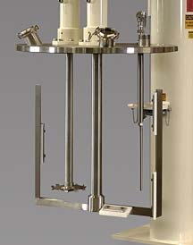
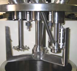
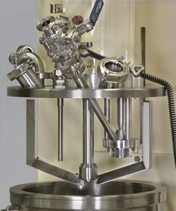
Multi-Shaft Mixer Sample Configurations